Performance
Operating Stress
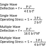
Compressing a wave spring creates bending stresses similar to a simple beam in bending. These compressive and tensile stresses limit the amount a spring can be compressed before it yields or “takes a set”. Although spring set is sometimes not acceptable, load and deflection requirements will often drive the design to accept some set or “relaxation” over time.
Maximum Design Stress
Static Applications: Smalley utilizes the Minimum Tensile Strength found within our tables of standard springs to approximate yield strength due to the minimal elongation of the hardened flat wire used in Smalley products. When designing springs for static applications we recommend the calculated operating stress be no greater than 100% of the minimum tensile strength. However, depending on certain applications, operating stress can exceed the minimum tensile strength with allowances for yield strength. Typical factors to consider are permanent set, relaxation, loss of load and/or loss of free height.
Dynamic Applications: When designing wave springs for dynamic applications, Smalley recommends that the calculation of operating stress not exceed 80% of the minimum tensile strength.
Residual Stress and Pre-Setting
Increasing the load capacity and/or fatigue life can be achieved by compressing a spring beyond its yield point or “presetting”. Preset springs are manufactured to a higher than needed free height and load and then compressed solid. Both the free height and load are reduced and the material surfaces now exhibit residual stresses, which enhance spring performance.
Fatigue
Fatigue cycling is an important consideration in wave spring design and determining precisely how much the spring will deflect can greatly impact the price of the spring. An analysis should include whether the spring deflects full stroke or only a few thousandths each cycle or possibly a combination of both as parts wear or temperature changes.
Formula:

| Fatigue Stress Ratio | Estimated Cycle Life |
| .00 < X < .40 | Under 30,000 cycles |
| .40 < X < .49 | 30,000 - 50,000 cycles |
| .50 < X < .55 | 50,000 - 75,000 cycles |
| .56 < X < .60 | 75,000 - 100,000 cycles |
| .61 < X < .67 | 100,000 - 200,000 cycles |
| .68 < X <.70 | 200,000 - 1,000,000 cycles |
| .70 < X | over 1,000,000 cycles |
Nomenclature
σ = Material tensile strength
S1 = Calculated operating stress at lower work height
S2 = Calculated operating stress at upper work height
You may use the Spring Design Calculator to quickly determine operating stresses and approximate cycle life, or the equations can be found on the Single Turn Gap or Overlap and Multiple Turn (Crest‑to‑Crest) Spirawave pages.
Load/Deflection
A comparison of the actual spring rate to the theoretical (calculated) spring rate provides practical limits for the working range of the spring. Spring rate (P/f) can be calculated by manipulating the deflection equations. Typically, theoretical rate is accurate until the spring starts to bottom out or reach its “solid height”.
As a general rule, the calculated spring rate is linear through the first 80% of available deflection and for work heights down to 2 times the solid height. Although the spring can operate beyond this “linear” range, measured loads will be much higher than calculated.
More information about Single Turn Gap or Overlap, Multiple Turn (Crest‑to‑Crest) Spirawave, and Nested Spirawave parts can be found on their pages.

Hysteresis
Wave springs exert a greater force upon loading and lower force upon unloading. This effect is known as hysteresis. The shaded area shows a graphic representation between the curves.
In a single turn spring, friction due to circumferential and radial movements are the prime causes. Crest-to-Crest and Nested Springs also contribute to the frictional loss as adjacent layers rub against each other. Sufficient lubrication will minimize this effect.

Diameter Expansion
Nested and Crest-to-Crest Spirawaves only: Multiple turn Spirawaves expand in diameter when compressed. The formula shown below is used to predict the maximum fully compressed diameter.
Formula:


Nomenclature
ODM = Outside diameter at solid (in)
R = Wave radius (in) = (4Y2 + X2)/8Y
N = Number of waves
θ = Angle = ArcSin[X/(2R)] (degrees)
b = Radial wall (in)
X = 1/2 wave frequency = (πDM)/(2N)
Y = 1/2 mean free height = (H-t)/2
Where H = Free height per turn (in)
Linear Springs
Linear Springs are a continuous wave formed (marcelled) wire length produced from spring temper materials. They act as a load bearing device having approximately the same load/deflection characteristics as a wave spring.
Forces act axially or radially depending on the installed position. Axial pressure is obtained by lying the expander flat in a straight line. Circular wrapping the expander (around a piston for example) produces a radial force or outward pressure.


Connect With Us